Ignition 2, GM HEI Distributor Notes
Before we get into the technical stuff I would like to present a tutorial on disassembling the GM HEI to familiarize you with the parts and possibly to help with future modifications.
Disassembly of the HEI distributor
With the unit out of the engine remove the distributor cap and rotor..
The key to taking the HEI apart is the roll pin that holds the drive gear to the distributor shaft. With a small hammer, a suitable punch, and a wooden block (I use the hardwood handle of my wire brush) carefully drive the pin out of the gear. Then pull the gear and thrust washers off the shaft. You can see the tang that is used to drive the oil pump.
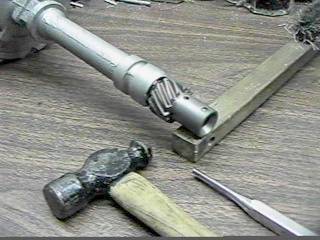
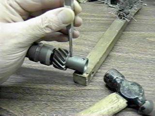
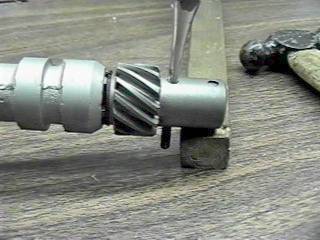
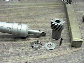
Then pull the shaft assembly out through the top of the distributor. Sometimes the shaft is gummed up with deposits so a little carburetor cleaner may be needed to free it.
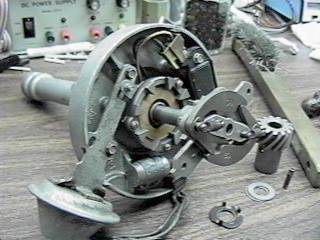
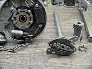
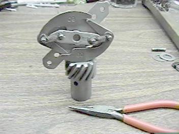
The shaft assembly is next. First carefully remove the springs and weights. Hold a fingertip on the end of the spring opposite the one you are pulling off the pin to prevent the spring from flying. Chances are you will never find it.
Then pull the E-clips from the inner spring shafts. Be on guard with special care here as these are lost more frequently than any other automotive part.
The advance cam can be pried carefully off with a small screwdriver. Go back and forth between the ends prying only a little at a time..
Then the rotor part of the reluctor can be slid off the shaft.
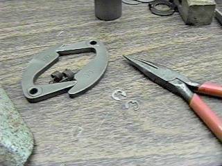
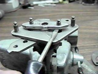
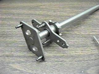
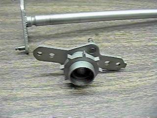
The vacuum advance module is attached with two screws. After taking out the screws the part seems trapped. A bump on the casting prevents the advance pushrod from pushing down out of the reluctor stator assembly until you pull it clear.
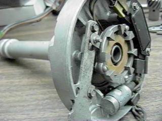
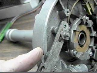
After pulling it clear of the bump push the end of the pushrod down with a pointed tool and rotate the assembly clockwise to remove it..
The reluctor/stator assembly is held onto the top bushing with a thin snap ring. Carefully pry it out and use extra care as this part can fly off too..
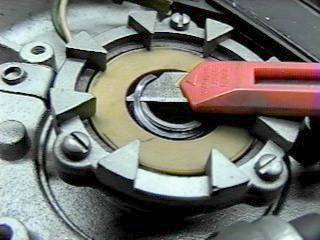
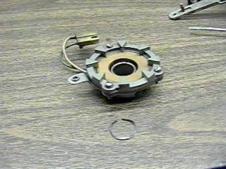
The control module and capacitor screws removed allows the whole wiring harness to lift free. Note the felt oil reservoir around the top bushing. GM soaks this felt in silicone oil (which does not evaporate) and it keeps the porous bushing lubricated.. Do not use ordinary oil on this felt. Chances are it does not need to be fooled with in any way.
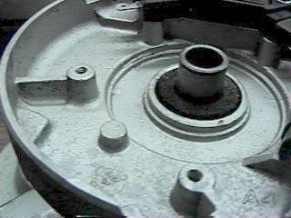
At this point we have the distributor taken to bits..
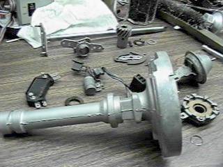
I have always disliked service manual writers saying “Reassembly is the reverse of the above procedure.” Or something equivalent. Now I am guilty of it myself.. Be careful and keep track of all the parts. Reassembly is the reverse of above procedures.
Now we go on to the technical stuff. Starting with the simplest procedure.
Distributor Shaft End Play
All of the HEI distributors I have fooled with have been set up from the factory with overly large clearances in the shaft end play. Too much clearance on the thrust bearing has the shaft and gear moving up and down during operation. This causes variations in timing due to the angle of the distributor drive gear. I measured the gear and calculated that the timing changes one degree for every 0.013 inch of endplay.
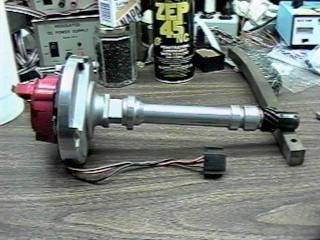
One important thing to notice when removing the distributor drive gear is the orientation of the index mark. Here is the proper location of the mark. You can see it lines up with the rotor.
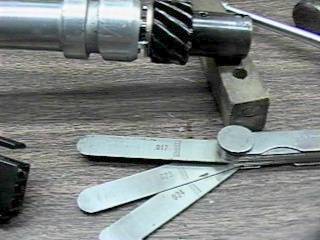
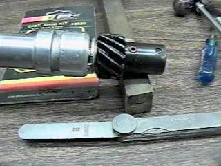
A feeler gauge is the proper tool for this job. This amount of end play would cause about five degrees of variation in the timing.
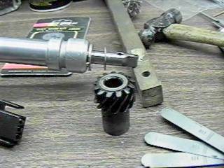
Shims to adjust this clearance are commonly available. Below is one of the kits on the market.
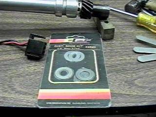
The thickest shim in the kit did the job as it was just right to bring the clearance down to 0.010 inches. First we see the shim going on and then the result with the correct clearance at 0.010 inches. This would keep the possible variation of timing from end play to less than one degree.
Vacuum Advance
The vacuum advance mechanism is not needed in an all-out racing application but makes a big difference on the street.
The pressure of the atmosphere is about 14.7 lbs per square inch or 30 inches of mercury. At low throttle openings such as during normal highway cruising the vacuum in the intake manifold is about 15 inches of mercury. (this will vary with the cam and other rodding modifications)
But consider that at 15 inches of vacuum in the manifold the effective air pressure filling the cylinder is only half of what would be available at full throttle. This means that a compression ratio of 9 to one is effectively reduced to about 4.5 to one..
At this low compression the fuel/air mixture burns much slower and for proper combustion the motor requires more ignition advance..
This is where the vacuum advance comes in.. At high vacuum the stock vacuum advance mechanism will provide about 20 degrees of additional ignition advance.. This makes a big difference on gas mileage as well as part throttle responsiveness. Both of these elements are important on the street. I have read that locking out the vacuum advance can reduce gas mileage by about 5 miles per gallon..
But when you start modifying your motor for performance the vacuum advance must be changed to fit in with the other changes to the HEI.. For maximum performance a lot more initial advance than the factory setting is required. Most stock specifications call for 4 to 8 degrees of initial advance. 12 to 16 degrees of initial advance would be better for performance.. And the centrifugal advance curve would start sooner.
Combining the 12 degrees of initial advance with about 8 degrees from the centrifugal advance and then adding 20 degrees from the vacuum can when operating at low throttle settings is just too much.. 40 degrees of total advance will probably cause pinging or even detonation.. That would be bad.
So losing the vacuum advance completely is probably not the best idea but it must be restricted to a reasonable amount of advance.. Adjustable vacuum advance modules are sold by several aftermarket sources and provide the best way of fixing this. But if you are on a tight budget a spacer or stop can be added to the stock vacuum advance to limit it.
Part throttle cruising in the stock configuration with 4 degrees of initial advance plus about 5 degrees of centrifugal advance and the 20 degrees from the vacuum can provides a reasonable overall advance of 29 degrees..
So in a performance setup with 12 degrees of initial and 8 degrees of centrifugal the vacuum advance should be limited to 10 degrees to keep the overall advance at 30 degrees or less..
There are many factors that influence the pinging tendency such as gasoline quality, cam timing, compression ratio, combustion chamber shape, spark plug heat range, engine temperature, part throttle load or lugging, and driving habits. So it is difficult to come up with anything more than a broad recommendation. You must test your own configuration and make adjustments based on what you find.
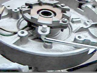
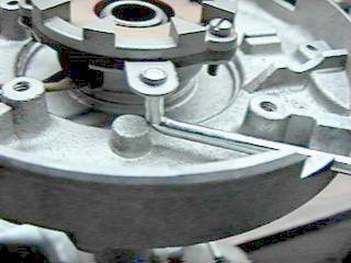
Here are a couple of pictures of naked vacuum advance operating rods showing the trick of removing the vacuum advance mechanism. First the rod in the normal operating position with the bump in the casting preventing it’s removal. Then the rod pulled out to clear the bump and the rod almost pushed out of the reluctor stator arm.
I ground the retaining flange off of a stock replacement 20 degree vacuum advance can to show you the internals. The assembly being held together by a finger which is out of the picture.
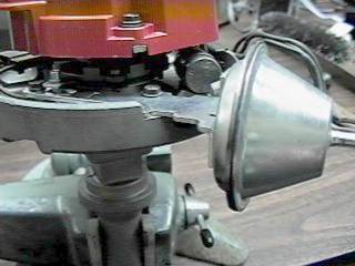
The diaphragm in the fully retarded position and then in the fully advanced position..
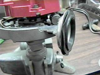
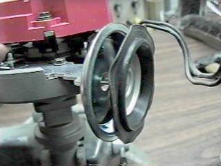
There is a the strong spring that forces the diaphragm to the retarded position.
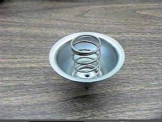
The pressure of the atmosphere pushes the diaphragm against the spring to advance the timing when the pressure is lowered on the other side.
In the centrifugal advance the rotor turns with the reluctor rotor so the posts in the distributor cap are always lined up with the rotor when the spark occurs. But the vacuum advance moves the reluctor stator to provide the additional advance and the design of the distributor cap and rotor have to take this possible misalignment into account..
These pictures are taken through a clear distributor cap to show the minimum vacuum advance alignment and maximum advance alignment of the rotor and posts..
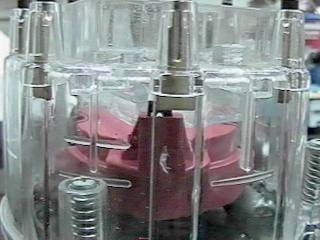
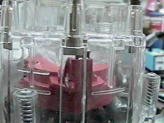
The pattern of burned spots on the distributor cap posts will indicate how much driving was done at high vacuum part throttle and low vacuum full throttle.. Remember, the rotor rotates in a clockwise direction looking down on the distributor.
Now we look at a ratty old stock vacuum advance mechanism. This is a 20 degree unit from a Chevrolet Suburban. You can see the 20 stamped into the frame with the spring code..
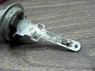
Most stock vacuum cans are 15 to 20 degrees. Those numbers are for crankshaft degrees and since the distributor rotates at ½ the speed of the crankshaft the actual advance at the distributor is half that.
Calculating based on the movement of the advance arm of the reluctor stator assembly, the amount of movement necessary for 20 degrees of crankshaft advance is about ¼ inch. (6 MM) I verified this by actually measuring the amount of movement against the spring in the 20 degree can. As you can see from the pictures that the movement is almost exactly ¼ inch..
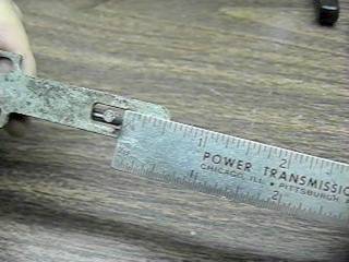
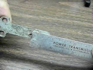
A good starting point on setting the vacuum advance for performance use would be about 10 degrees of crankshaft advance. This is about 1/8 inch (about 3 MM) of movement of the control rod.
Centrifugal Advance
First let’s talk about why this device is in your HEI.. An internal combustion engine develops best power if the cylinder pressure peak occurs just after Top Dead Center (TDC) on the power stroke.. The air fuel mixture takes time to burn and develop pressure so the spark is set to occur just before TDC. As rpm increases the time allowed for the combustion is lessened so the spark timing has to be advanced. This is where the centrifugal advance comes in.
How does it work?
Getting way back to basics with old Isaac Newton.. You may remember that he said that an object once in motion will continue in a straight line unless acted on by an external force.. This is his first law of motion.
Think about those weights on the advance mechanism now.. They are trapped on the spinning distributor shaft. One end is on a pivot pin and must follow the circle no matter how much it wants to go in a straight line. The other end is caught by a hooked end that snags on a spring loaded cam. As the speed of the shaft increases the force required to hold the weight back increases rotating the cam and stretching the spring.
Now there is a big problem.. It seems that as the speed increases the forces involved increase much faster than the speed. At the square of the speed to be exact. This is not my fault, blame Isaac.. So the force required to hold the weights going in a circle is increasing much too fast. The motor just needs the advance to increase directly as the speed and not as the square of the speed.
This is where the really smart advance cam comes in. That little gizmo can actually calculate the square root of the force and provide the answer with the turning of the reluctor rotor in relation to the distributor shaft. The ignition rotor is along for the ride so the spark goes to the right place in the distributor cap and it all works great. First the system at idle, then at intermediate rpm, and then at full rpm.. Note how the cam, rotor mount, and underneath the reluctor rotor are advancing in relation to the shaft.
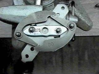
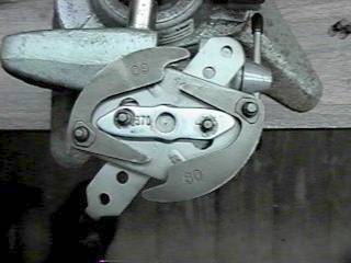
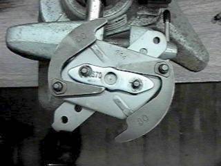
But the timing of the curve for reliability and mileage is not the same as the timing of the curve for performance and so springs, weights, and even square root cams may have to be changed.
In most cases for a street performance car having the centrifugal advance set so the curve starts above idle and reaches it’s maximum at about the torque peak of the motor. There are so many factors that vary in this part of the tuning that trying various curves and testing performance is the best way of setting the centrifugal advance curve.
The typical advance curve is a straight line between the onset of advance and the maximum reached. You can measure these points easily with an ordinary powered timing light and do not need to invest in the more expensive (and inaccurate) dial-back timing light.
With the motor warmed up and the vacuum advance disconnected and plugged it is easy to see the point where the centrifugal advance starts by observing the TDC mark moving past the timing tab.
To find the other end of the timing curve requires a clear mark on the vibration damper at 30 degrees before top dead center.. On an eight inch damper the mark should be 2.094 inches from the TDC mark. That is about 2 3/32”. A flexible scale does a good job on the curved surface. You can see that I also painted the damper two colors so it would be obvious if the outer ring slipped on the rubber retainer.
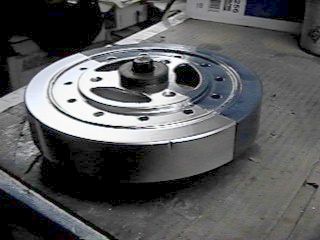
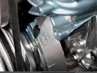
By having someone observe the rpm and watch the 30 degree mark end it’s movement as rpm increases you can find the top point on the advance curve. Most powered timing lights can go up to the rpm necessary..
On my mild 350 Chevy motor (about 350hp) I have the centrifugal advance starting at about 1000 rpm and all in at 3400 rpm. By testing with the G-Tech meter I could establish what worked best for this motor.
If the springs are so light that your advance curve starts at the normal idle speed it causes an instability in the idle that cannot be tuned out.. I know this from personal experience.
HEI Coil and Ignition Module
The HEI coil is the device that actually generates the high voltage needed to fire the sparkplugs.. In some cases it can generate up to 40,000 volts. Usually only about 12,000 volts is needed but having the extra voltage means that the ignition will be reliable under all circumstances. And it makes the sensation of being shocked much more intense. Be careful with these high voltage systems as they can be hazardous to your health.. And unnecessarily stimulating.
The coil is one area that needs upgrading in a performance application. The stock system only generates full voltage under about 4150 rpm due to the time necessary to charge the magnetic field in the coil being about 3.6 to 4 milliseconds. With the voltage dropping rapidly above 4200rpm by the time the motor reaches 5500 rpm the HEI ignition is no longer reliable. This is not a problem in stock motors and normal driving but is inadequate for racing.
The charging time of the coil is directly related to the charging current. One of the reasons for the slow charge time specified during the initial design of the HEI was that the early transistors used in the control module were limited in the amount of current they could handle. Times have changed in the last 30 years and modern control modules are much more capable.
The performance coils (using matching control modules) charge in about 2.5 milliseconds which means that they can develop full voltage up to 6000 rpm and useable voltage up to 7200 rpm.
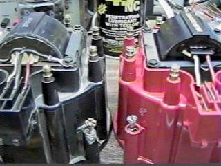
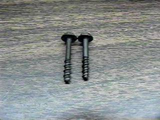
To be able to charge this quickly the performance coils are constructed differently with smaller cores and fewer primary windings. The smaller cores can cause a serious problem if the longer screws used to mount the stock coils are reused for a performance coil. Since they would be too long they may crack the distributor cap and cause problems later. You can see the stock coil on the left with the performance coil on the right. Note the thinner core of the performance coil.
Here is the difference in the mounting screws. Watch out for this..
Since the current necessary to run the performance coil and module is so much higher the condition of the wire and connector to the distributor is important. When converting from points type distributors to HEI it is necessary to replace the resistance wire or resistor with plain copper 10 gauge wire. Otherwise the HEI distributor only gets about 9 volts and would give miserable performance. This issue caused many early rodders to condemn the HEI as unsuitable for performance use..
The high current modern HEI generates a lot of heat in the control module and it is essential that heat conducting grease is used beneath the module to allow the heat to be passed to the aluminum housing.
To work correctly at high rpm’s the coil and module should be matched. If a high performance coil is used with the standard module it may not be able to function as well as with a matching module. With some combinations the module may overheat and fail. However if a standard coil is used with a high performance module it will work but will probably not perform much better than stock. The charge time of the coil is the critical factor..
Rick Draganowski
Gold Beach, Oregon